- 您现在的位置:买卖IC网 > Sheet目录477 > MICRF600DEV1 (Micrel Inc)KIT DEV RADIOWIRE 902-928MHZ
�� �
�
�Micrel,� Inc.�
�MICRF600/MICRF600Z�
�Writing� to� the� Control� Registers� in� MICRF600�
�Writing:� A� number� of� octets� are� entered� into� MICRF600,�
�followed� by� a� load-signal� to� activate� the� new� setting.�
�Field�
�Address:�
�R/W� bit:�
�Values:�
�Comments�
�7� bit� =� A6,� A5,� …A0� (A6� =� msb.� A0� =� lsb)�
�“0”� for� writing�
�8� bits� =� D7,� D6,� …D0� (D7� =� msb,� D0� =� lsb)�
�Making� these� events� is� referred� to� as� a� “write� sequence.”� It�
�is� possible� to� update� all,� 1,� or� n� control� registers� in� a� write�
�sequence.� The� address� to� write� to� (or� the� first� address� to�
�write� to)� can� be� any� valid� address� (0-21).� The� IO� line� is�
�always� an� input� to� the� MICRF600� (output� from� user)� when�
�writing.�
�Table� 3.� “Address”� and� “R/W� bit”� together� make� 1� octet.�
�In� addition,� 1� octet� with� programming� bits� is� entered.� Totally,� 2�
�octets� are� clocked� into� the� MICRF600.�
�How� to� write:�
�?� Bring� CS� high�
�What� to� write:�
�?� The� address� of� the� control� register� to� write� to� (or� if�
�more� than� 1� control� register� should� be� written� to,�
�the� address� of� the� 1� st� control� register� to� write� to).�
�?�
�?�
�Use� SCLK� and� IO� to� clock� in� the� 2� octets�
�Bring� CS� low�
�?�
�A� bit� to� enable� reading� or� writing� of� the� control�
�registers.� This� bit� is� called� the� R/W� bit.�
�CS�
�SCLK�
�?�
�The� values� to� write� into� the� control� register(s).�
�IO�
�A6�
�A5�
�A0�
�RW�
�D7�
�D6�
�D2�
�D1�
�D0�
�Field�
�Comments�
�Address:�
�R/W� bit:�
�A� 7-bit� field,� ranging� from� 0� to� 21.� MSB� is� written� first.�
�A� 1-bit� field,� =� “0”� for� writing�
�Address� of� register� i�
�RW�
�Data� to� write� into� register� i�
�Internal� load� pulse� made� here�
�Values:�
�A� number� of� octets� (1-22� octets).� MSB� in� every� octet� is� written�
�first.� The� first� octet� is� written� to� the� control� register� with� the�
�specified� address� (=”Address”).� The� next� octet� (if� there� is� one)� is�
�written� to� the� control� register� with� address� =� “Address� +� 1”� and� so�
�on.�
�Table� 2.� Writing� to� the� Control� Registers�
�How� to� write:�
�Bring� CS� active� to� start� a� write� sequence.� The� active� state�
�of� the� CS� line� is� “high.”� Use� the� SCLK/IO� serial� interface� to�
�clock� “Address”� and� “R/W”� bit� and� “Values”� into� the�
�MICRF600.� MICRF600� will� sample� the� IO� line� at� negative�
�edges� of� SCLK.� Make� sure� to� change� the� state� of� the� IO�
�line� before� the� negative� edge.� Refer� to� figures� below.�
�Bring� CS� inactive� to� make� an� internal� load-signal� and�
�complete� the� write-sequence.�
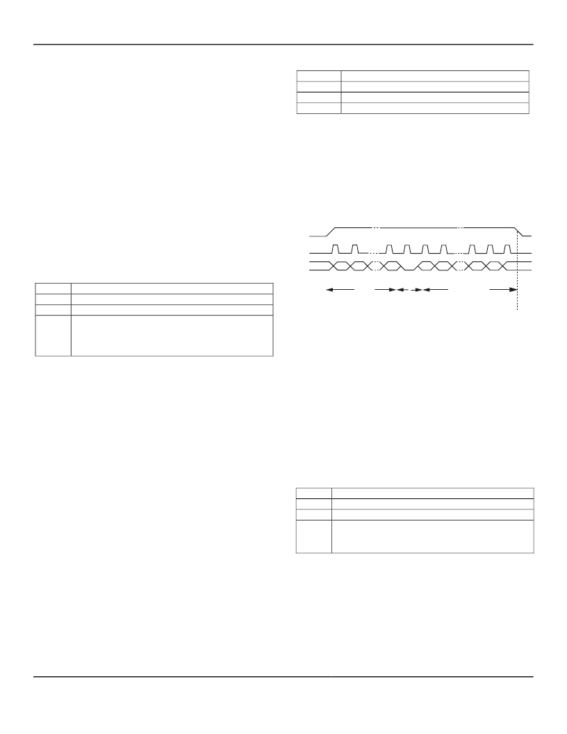
�Figure� 1.� How� to� write� to� a� single� Control� Register�
�In� Figure� 1,� IO� is� changed� at� positive� edges� of� SCLK.� The�
�MICRF600� samples� the� IO� line� at� negative� edges.� The�
�value� of� the� R/W� bits� is� always� “0”� for� writing.�
�Writing� to� All� Registers�
�After� a� power-on,� all� writable� registers� must� be� written.�
�This� is� described� here.�
�Writing� to� all� register� can� be� done� at� any� time.� To� get� the�
�simplest� firmware,� always� write� to� all� registers.� The� price�
�to� pay� for� the� simplicity� is� increased� write-time,� which�
�leads� to� increased� time� for� changing� the� way� the�
�MICRF600� works.�
�What� to� write�
�The� two� different� ways� to� “program� the� chip”� are:�
�Field�
�Comments�
�?�
�?�
�Write� to� a� number� of� control� registers� (0-22)� when�
�the� registers� have� incremental� addresses� (write� to�
�1,� all� or� n� registers)�
�Write� to� a� number� of� control� registers� when� the�
�registers� have� non-incremental� addresses.�
�Address:� ‘000000’� (address� of� the� first� register� to� write� to,� which� is� 0)�
�R/W� bit:� “0”� for� writing�
�Values:� 1� st� Octet:� wanted� values� for� ControlRegister0.� 2� nd� Octet:� wanted�
�values� for� ControlRegister1� and� so� on� for� all� of� the� octets.� So� the�
�22� nd� octet:� wanted� values� for� ControlRegister21.� Refer� to� the�
�specific� sections� of� this� document� for� actual� values.�
�Table� 4.� “Address”� and� “R/W� bit”� together� make� 1� octet.�
�Writing� to� a� Single� Register�
�Writing� to� a� control� register� with� address� “A6.� A5,� …A0”� is�
�described� here.� During� operation,� writing� to� 1� register� is�
�sufficient� to� change� the� way� the� transceiver� works.� Typical�
�example:� Change� from� receive� mode� to� power-down.�
�In� total,� 23� octets� are� clocked� into� the� MICRF600.�
�July� 2006�
�8�
�M9999-082505�
�发布紧急采购,3分钟左右您将得到回复。
相关PDF资料
MK01-C
SENSOR REED SPST-NO SMD
MK01-H
SENSOR REED SPDT-CHANGE SMD
MK02/0-1A66-500W
SENSOR REED SPST-NO
MK02/6-0
SENSOR REED PCB 24MM T/H
MK03-1C90C-500W
SENSOR REED SPDT CYLINDER
MK05-1A66C-500W
SENSOR REED SPST-NO SCREW MOUNT
MK06-6-A
SENSOR REED SPST-NO SIL T/H
MK06-6-E
SENSOR MAGNETIC PC MNT SPST-N/O
相关代理商/技术参数
MICRF600TR
制造商:MICREL 制造商全称:Micrel Semiconductor 功能描述:902-928MHz ISM Band Transceiver Module
MICRF600Z
功能描述:TXRX ISM 902-928MHZ 11.5X14.1MM RoHS:是 类别:RF/IF 和 RFID >> RF 收发器 系列:RadioWire® 产品培训模块:Lead (SnPb) Finish for COTS
Obsolescence Mitigation Program 标准包装:30 系列:- 频率:4.9GHz ~ 5.9GHz 数据传输率 - 最大:54Mbps 调制或协议:* 应用:* 功率 - 输出:-3dBm 灵敏度:- 电源电压:2.7 V ~ 3.6 V 电流 - 接收:* 电流 - 传输:* 数据接口:PCB,表面贴装 存储容量:- 天线连接器:PCB,表面贴装 工作温度:-25°C ~ 85°C 封装/外壳:68-TQFN 裸露焊盘 包装:管件
MICRF600Z TR
功能描述:TXRX ISM 902-928MHZ 11.5X14.1MM RoHS:是 类别:RF/IF 和 RFID >> RF 收发器 系列:RadioWire® 产品培训模块:Lead (SnPb) Finish for COTS
Obsolescence Mitigation Program 标准包装:30 系列:- 频率:4.9GHz ~ 5.9GHz 数据传输率 - 最大:54Mbps 调制或协议:* 应用:* 功率 - 输出:-3dBm 灵敏度:- 电源电压:2.7 V ~ 3.6 V 电流 - 接收:* 电流 - 传输:* 数据接口:PCB,表面贴装 存储容量:- 天线连接器:PCB,表面贴装 工作温度:-25°C ~ 85°C 封装/外壳:68-TQFN 裸露焊盘 包装:管件
MICRF610
制造商:MICREL 制造商全称:Micrel Semiconductor 功能描述:868-870MHz ISM Band Transceiver Module
MICRF610_0608
制造商:MICREL 制造商全称:Micrel Semiconductor 功能描述:868-870MHz ISM Band Transceiver Module
MICRF610DEV1
制造商:Micrel Inc 功能描述:DEVELOPMENT KIT TRANSCEIVER 868MHZ
MICRF610TR
制造商:MICREL 制造商全称:Micrel Semiconductor 功能描述:868-870 MHz ISM Band Transceiver Module
MICRF610Z
功能描述:IC RF MOD 868-870MHZ 11.5X14.1MM RoHS:是 类别:RF/IF 和 RFID >> RF 收发器 系列:- 产品培训模块:Lead (SnPb) Finish for COTS
Obsolescence Mitigation Program 标准包装:30 系列:- 频率:4.9GHz ~ 5.9GHz 数据传输率 - 最大:54Mbps 调制或协议:* 应用:* 功率 - 输出:-3dBm 灵敏度:- 电源电压:2.7 V ~ 3.6 V 电流 - 接收:* 电流 - 传输:* 数据接口:PCB,表面贴装 存储容量:- 天线连接器:PCB,表面贴装 工作温度:-25°C ~ 85°C 封装/外壳:68-TQFN 裸露焊盘 包装:管件